
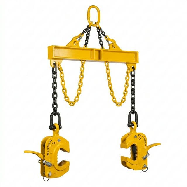
Lifting Magnets vs. Plate Clamps: A Procurement, Throughput, and Safety Decision Guide
Compare lifting magnets vs. plate clamps for steel handling: material limits, cycle-time assumptions, safety checks, and three-year TCO. Prepare your RFQ.
Lifting magnets vs. plate clamps: which should you specify? Start with the material, lifting orientation, and permitted contact marks. Magnets are candidates for ferromagnetic plate with accessible top surfaces and a documented capacity at the actual thickness and air gap. Clamps are candidates where edge access is available and the exact model covers the plate's hardness, jaw opening, load, and orientation. Neither attachment wins every application.
For procurement teams, production engineers, and safety managers, the useful comparison comes after both options pass those checks: how much rigging time, labor, inspection, and surface rework does each require in your shop?
Last reviewed: October 26, 2026.
Scope: Global, English-language screening for below-the-hook steel plate handling in fabrication shops, steel warehouses, cutting centers, and shipyards. US and European standards are reference frameworks; applicable law and adopted editions depend on the installation country.
Limit: This is a supplier-published decision guide, not an independent product test, lift authorization, or compliance certificate. Use the manufacturer's manual and a competent person's site-specific lift plan. Cost and cycle-time figures below are explicit modeling assumptions, not measured customer results.
Preparing a purchase? Send your plate-handling requirements for an application review, using the RFQ checklist below.
1. Operating Mechanics: Friction Grip vs. Magnetic Flux Loop
Mechanical Plate Clamps: Check the Exact Cam and Load Range
A serrated-cam plate clamp converts load on its lifting eye into gripping force at the plate edge. Its suitability depends on the jaw mechanism, tooth engagement, plate condition, and approved lifting direction. A simplified friction model cannot establish its rated working load limit (WLL).
Hardness limits are model-specific. For example, Crosby's IPU10 family lists 345 HB for the standard IPU10 and 450 HB for the IPU10H. These are different product ratings, not a universal 300 HB cutoff. Confirm the exact clamp variant against the plate specification.
Minimum load is also model-specific. That same family generally lists 10% of maximum WLL, with 5% exceptions for specified models or material conditions. An oversized clamp may fall outside its permitted range even when the load is below its maximum rating. Check the load carried by each clamp, including the approved sling arrangement.
Lifting Magnets: Check the Workpiece as Part of the Circuit
A magnetic lifter closes a magnetic circuit through a ferromagnetic workpiece. An idealized normal attraction model is F = B² × A / (2 × μ₀), where B is interface flux density, A is effective pole area, and μ₀ is the permeability of free space. It explains why reduced contact flux matters; it does not calculate a safe lifting capacity for a real plate.
Two practical boundaries dominate selection:
- Thickness and flexibility: Thin material can limit the available holding force and allow flux to reach a second sheet. Long, flexible plate can peel away from the poles as it bends.
- Contact and air gap: Scale, paint, rust, bowing, and debris change pole contact. Use the exact supplier's thickness, material, temperature, and air-gap ratings; there is no universal percentage loss per millimeter.
Magnets avoid the tooth penetration required by serrated clamps. However, alloy composition, heat treatment, and magnetic properties can change capacity: do not assume a wear plate has the same rating as mild steel. Eclipse's Ultralift Plus illustrates a manually switched permanent lifter with an interlocked handle and a product-specific safety-check method. Its specifications do not apply automatically to other lifters.
2. Technical Comparison Matrix: Magnets vs. Clamps
Use this matrix to screen candidates before comparing price. Every column still requires a model-specific manual and lift-plan review.
| Evaluation Parameter | Mechanical Plate Clamps | Permanent Magnetic Lifters (PML) | Electro-Permanent Systems (EPM) |
|---|---|---|---|
| Standards and documentation | Confirm applicable attachment standard and model certificate | Confirm applicable magnet standard and model certificate | Confirm magnet, beam, and control-system documentation |
| Proof load vs. breakaway | Proof-test ratio is not an allowable overload | Breakaway force is not WLL; check rated conditions | Verify system rating and magnetization confirmation |
| Gripping interface | Edge access within rated jaw opening | Top contact with matched pole geometry | One or multiple top-contact magnetic modules |
| Surface preservation | Serrated models may leave indentations | Avoids tooth marks; debris or sliding may still mark steel | Avoids tooth marks; inspect every contact point |
| Material hardness | Exact cam model determines permissible hardness | Verify alloy and heat-treatment effects on capacity | Verify actual grade and magnet configuration |
| Non-ferrous material | Possible only with a model approved for that material | Unsuitable for aluminum, copper, or brass | Unsuitable for aluminum, copper, or brass |
| Lifting orientation | Horizontal, vertical, and turning require the appropriate model | Use only directions expressly rated in the manual | Turning requires a system expressly designed for it |
| Stack access | Usually needs room to insert jaws | Top access; single-sheet pickup must be verified | Separation and sensing may be engineered into the system |
| Crew requirement | Determined by placement, visibility, and lift plan | Manual handle access is still required | Remote control may reduce close approach; staffing remains site-specific |
| Rigging time | Time the complete attach/check/release process on site | Include placement, safety checks, and manual switching | Include contact checks, switching confirmation, and sheet separation |
| Power loss | Grip depends on mechanism and approved loading | Holding field needs no electrical supply | A confirmed permanent magnetic state can retain load after supply loss; check the exact system |
| Key hazards | Incorrect latch use, minimum-load violations, damaged cams, unsuitable surfaces | Peeling, air gaps, incorrect material or thickness, unintended release | The same contact hazards plus control/interlock faults |
Procurement distinction: A proof test, a structural design factor, and a magnetic breakaway ratio describe different things. Do not combine them into a single “mandatory safety factor” or multiply a nameplate WLL to authorize a larger lift. ASME B30.20 covers below-the-hook devices; the contractual edition and applicable requirements must be confirmed for the project.
3. Visual Architecture: Gripping Mechanics & Force Distribution
This schematic shows contact locations and selection hazards. It is not a load-path calculation or evidence of tested performance. On narrow screens, scroll horizontally to read the labels.
4. Throughput, Labor Economics, and 3-Year TCO Modeling
Compare quotations for attachments that handle the same plate envelope and duty. A manual PML pair and an automated EPM spreader are different systems; their purchase price, staffing, and control scope should not be treated as interchangeable.
Measure the Rigging Task Before Crediting Savings
Record placement, attachment, lock or magnetization checks, initial lift verification, set-down, and release. Measure crane travel separately. Repeat on representative plate sizes and surface conditions; record the crew actually occupied during each task. A manual magnet still needs an operator at its handle, while remote EPM operation does not automatically eliminate floor assistance.
The model below assumes two people occupied for 90 seconds per clamp cycle versus two people occupied for 18 seconds per magnetic-system cycle. The same crew count isolates the time assumption; it is not a staffing recommendation or a promise that every magnetic system achieves this speed.
Reproducible 3-Year TCO Example
Hypothetical inputs, USD: 80 lifts per shift × 2 shifts per day × 250 working days = 40,000 lifts/year. Both options are assumed to pass engineering selection. Equipment prices, task times, rework budgets, and maintenance allowances are illustrative inputs, not market quotations or observed results.
| Cost Component | Dual Mechanical Plate Clamps | Candidate Magnetic System | Difference / Basis |
|---|---|---|---|
| Initial installed CapEx | $1,800 | $12,500 | $10,700 magnetic premium; replace with like-for-like quotes |
| People occupied per task | 2 | 2 | Same accounting basis; site determines safe staffing |
| Assumed rigging time per lift | 90 seconds | 18 seconds | Excludes travel and common process time |
| Annual rigging elapsed time | 1,000 hours | 200 hours | 40,000 × seconds ÷ 3,600 |
| Annual person-hours | 2,000 | 400 | Elapsed time × 2 people |
| Labor allocation at $35/person-hour | $70,000 | $14,000 | $56,000/year in released labor capacity |
| Assumed annual rework budget | $9,000 | $1,000 | $8,000/year difference; magnetic handling is not damage-free |
| Assumed annual maintenance | $850 | $200 | $650/year difference; include actual inspection and service scope |
| Annual modeled operating cost | $79,850 | $15,200 | $64,650/year difference |
| Cumulative 3-year modeled spend | $241,350 | $58,100 | $183,250 difference after initial CapEx |
Formula: three-year spend = installed CapEx + 3 × (allocated labor + rework + maintenance). Simple payback under these assumptions is $10,700 ÷ $64,650 × 12 = 1.99 months.
Interpretation: This is an undiscounted partial TCO model. It excludes tax, financing, energy, training, downtime, and any beam/control integration not included in the quoted installed price. Released time becomes cash savings only if payroll, overtime, or purchased capacity actually falls. Do not count the same time again as a separate crane saving.
Sensitivity: If no labor saving can be realized, only the assumed $8,650 annual rework and maintenance difference remains; payback becomes 14.84 months. If that difference is also unverified, the business case is not yet established. Replace assumptions with measured trials and supplier quotations before approval.
5. Critical Safety Failure Modes: Slack-Line vs. Peeling Deflection
Mechanical Clamps: Loading, Locks, and Surface Suitability
A change in tension or unintended contact during travel can disturb a load. Inspect the latch, cam, pivot, and gripping surfaces as specified in the clamp manual. Locking mechanisms differ; do not assume either that all clamps release under slack load or that a latch makes every loading condition acceptable.
Oil, loose scale, worn teeth, out-of-range hardness, and incorrect jaw opening can defeat the intended grip. Follow the exact manufacturer's cleaning and material restrictions. Stop if the plate condition is outside the documented operating envelope.
Lifting Magnets: Peeling, Contact, and Control State
A long plate lifted at too few points can bend away from the poles. Our thin steel plate lifting guide provides related screening context; the selected system still needs approved support spacing and load geometry.
Scale, paint, rust, and bowing introduce air gaps. Do not use an inverse-square shortcut or a generic air-gap threshold to calculate WLL. See the air gap and surface roughness derating guide, then obtain the exact model's derating data for the actual plate.
For EPM systems, distinguish supply loss after confirmed magnetization from interrupted switching, a release command, damaged hardware, and poor contact. Eclipse's Optimag E documents a permanent holding state and a magnetization interlock for that product. This does not make every EPM system immune to a dropped load. Continuously powered electromagnets are a separate category with their own power-loss protection requirements.
Selection hold point: If orientation, load distribution, gripping condition, or magnetization status cannot be confirmed, pause selection and resolve it with the supplier and competent person before lifting.
6. Industrial Application Decision Framework
CNC Fiber Laser & Plasma Cutting Tables
Screen magnets first for top access. They can avoid the edge clearance needed by clamps. Confirm that the pole arrangement suits the intact sheet, cut skeleton, or individual part being handled. Perforations and loose cutouts change the task; a rating for intact plate does not approve skeleton lifting. Measure changeover time rather than assuming a percentage productivity gain.
Vertical Plate Storage & Plate Turning
Screen a rated vertical or universal clamp, or a purpose-designed magnetic turning system. A magnet rated for horizontal plate handling does not gain a vertical WLL by applying a generic friction percentage. Check the complete load path throughout the turn, including approved angles, support, and release position.
High-Hardness Wear Plate
Compare a suitably rated clamp with a magnet qualified for the exact steel. The standard cam's hardness limit may exclude it, but specialist clamps exist. Magnetic suitability also needs material-specific confirmation; hardness alone neither disqualifies nor approves a lifter.
Austenitic Stainless & Non-Ferrous Alloys
Screen material-approved clamps or vacuum equipment. Do not treat a weak magnetic response in cold-worked 304/316 stainless as proof of a lifting rating. Aluminum, brass, and copper cannot be lifted directly by these magnetic lifters. Check marking limits and the chosen alternative's material and surface requirements.
Long, Flexible Plates
Request an engineered support arrangement. Multiple magnetic modules or an appropriate clamp-and-beam arrangement may control deflection. Neither a fixed “4–8 magnets” rule nor plate length alone determines safe spacing. Ask the supplier to document the worst-case plate thickness, deflection, load sharing, and permitted acceleration.
7. The Procurement & Engineering RFQ Checklist
Give competing suppliers the same application envelope so their ratings and prices can be compared:
- Material and marking limits: Exact grade, heat treatment, hardness range, and whether cam impressions or pole-contact marks are acceptable.
- Dimensions and mass: Minimum/maximum thickness, length, width, mass, holes, cutouts, flatness, and center-of-gravity variation.
- Contact conditions: Scale, rust, oil, paint thickness, temperature, and photographs. Request model-specific capacity or restrictions for those conditions.
- Orientation and support: Horizontal transfer, vertical retrieval, or turning; required support points, sling angles, load sharing, and travel clearance.
- Destination requirements: Installation country, applicable legislation, and agreed standard editions such as ASME B30.20 or EN 13155. Ask for conformity documentation, test records, identification, and instructions applicable to the supplied system; agree any independent witnessing separately.
- Operating limits and controls: Rated maximum and any minimum load, jaw range, latch or handle interlock, magnetization confirmation, power-loss behavior, and safe release sequence.
- Capacity evidence: Distinguish WLL, proof load, and breakaway force. Request the test conditions and derating charts rather than a universal safety-factor claim.
- Lifecycle and acceptance: Inspection intervals, replacement criteria, spares, training, installed scope, representative trial plates, measured rigging times, and the staffing approved by the lift plan.
Use these completed inputs when requesting a technical quotation; they are more useful than a maximum tonnage alone.
8. Frequently Asked Questions (FAQ)
Can a standard lifting magnet turn a steel plate from horizontal to vertical?
Only if the manufacturer's rating expressly covers that operation and the complete arrangement. A horizontal plate-lifting WLL does not establish shear or turning capacity. Use a rated turning attachment and an approved procedure; do not estimate capacity as a fixed percentage of breakaway force.
Will mechanical plate clamps create micro-cracks in pressure vessel steel?
Serrated cams can leave indentations, but this alone does not prove cracking or a blanket code prohibition. Ask the responsible fabrication or quality engineer whether impressions are permitted under the project's material, fatigue, and inspection requirements. If marks are unacceptable, evaluate a suitable non-marking attachment.
Can an EPM drop a plate if its electrical cable is severed?
A permanent magnetic state can retain its field after supply loss once switching is complete, as documented for Optimag E in the sources below. A severed cable still requires a safe recovery procedure. Interrupted switching, an unintended release signal, mechanical damage, and loss of pole contact remain separate hazards; obtain the exact system's fault behavior.
Why can a mechanical plate clamp slip on oily steel?
Oil can interfere with the intended gripping contact. The effect depends on the clamp and surface, so a generic friction calculation cannot approve the lift. Clean or reject the surface as directed by the manual, or obtain written confirmation that the selected model covers the condition.
How can I avoid picking up two thin sheets with a lifting magnet?
Specify the actual sheet thickness, grade, coating, and stack conditions. Ask for a single-sheet handling system, suitable separation equipment, and a documented method of confirming that only one sheet is carried before travel. Shallow-field magnets and sheet separators are possible design options, not guarantees for every stack.
Do all plate clamps require at least 10% of rated WLL?
No. Crosby's cited IPU10 family lists 10% for many variants and 5% for specified exceptions. Other clamps may have different limits. Verify the exact model, material condition, and load on each clamp against its manual.
Sources & Industry References
Reviewed October 26, 2026. Manufacturer pages below are product examples, not independent comparisons or ratings for LiftMagnetics products. The cost model is our disclosed arithmetic scenario; these sources do not substantiate its assumed prices or productivity.
- ASME B30.20 — Below-the-Hook Lifting Devices. Official standard scope and publisher record, listing the 2025 edition at review. The public summary is not a substitute for the adopted standard or project compliance review.
- Kito Crosby — IPU10 / IPU10J / IPU10S / IPU10H. Product-specific hardness limits, minimum-load exceptions, rated turning use, identification, and proof-test information. Follow the manual for the selected variant.
- Eclipse Magnetics — Ultralift Plus Magnetic Lifter. Example of manual permanent switching, handle interlocks, and a product-specific safety-shim check. No inference that all magnets share its rating.
- Eclipse Magnetics — Optimag E Electronically Switchable Permanent Magnets. Product documentation for switching-only power, retained magnetic state after supply loss, and magnetization confirmation.
Specify the Right Below-the-Hook Solution with LiftMagnetics
Use the material and orientation checks to shortlist a suitable attachment, then compare complete quotations using measured task times. If a key rating is missing, resolve it before assigning financial savings.
Contact LiftMagnetics for an application review with your completed RFQ checklist, plate photographs, and destination country. Ask for the proposed model, operating limits, test documentation, and installed scope. You can also browse our industrial lifting products and heavy-duty permanent magnetic lifters before requesting a technical quotation.
More Posts

Battery Lifting Electromagnets vs EPMs: Procurement Guide
Compare battery-powered lifting electromagnets vs EPMs for safety, TCO, power-loss behavior, duty-cycle limits, battery upkeep, and RFQ checks before you buy.

Buyer RFQ Email Examples (Good vs Bad)
Practical B2B examples showing why some magnetic lifter RFQ emails fail and how to write high-quality inquiry emails that suppliers can quote quickly.
How to Choose Lifting Magnets for Cylindrical & Round Steel Loads
Choose lifting magnets for cylindrical and round steel loads. Compare V-groove poles, derating factors, pipe limits, RFQ checks, and contact engineering.