
Magnetic Steel Coil Lifting: Eye-to-Sky vs. Eye-Horizontal Handling, Telescoping Prevention, and C-Hook Replacement
Compare magnetic steel coil lifting orientations, telescoping risks, and C-hook alternatives. Use the engineering checklist to prepare your application review.
Can a lifting magnet handle a steel coil eye-to-sky without the inner wraps sliding out? A purpose-designed coil lifter may do so within a documented operating envelope, but neither an electro-permanent magnet (EPM) label nor a nominal tonnage rating establishes suitability. Magnetic steel coil lifting requires checking the orientation, contact geometry, condition of individual wraps, and retention of the complete coil. A plate-lifting rating cannot be transferred to a wound coil.
For steel service center managers, crane engineers, and procurement teams, the useful question is which handling arrangement fits the entire route from receiving to storage and decoiling. Eye-to-sky handling can avoid inserting a hook into the bore. Eye-horizontal handling can preserve the orientation needed at an uncoiler. Either arrangement needs application-specific engineering; changing orientation may also require a separate rated upender.
Published and reviewed: November 5, 2026.
Scope: Global, English-language selection guidance for ferromagnetic steel coils. Examples address procurement and engineering screening, rather than approval of any particular load or equipment model. Applicable local law, the specified standard edition, manufacturer instructions, and the plant lifting plan govern the actual operation.
Evidence and limits: The comparison tables are qualitative decision aids. The numerical examples are explicitly hypothetical calculations, not measured factory results, load ratings, supplier quotations, or customer savings. No coil trials or independent product certification records are presented here.
Preparing an RFQ? Send your coil envelope, orientation, and crane details for an application review, using the checklist below.
1. Executive Summary & Core Engineering Principles
A wound coil differs from a solid steel block. Its adjacent strip wraps can move relative to one another, while coatings, winding tension, and edge alignment vary across incoming stock. The lifting arrangement must retain the complete load throughout pickup, travel, and landing.
Four principles help separate a credible proposal from a generic capacity claim:
- Define the orientation first. Eye-to-sky means the bore axis is vertical and the accessible lifting surface is usually the upper annular face. Eye-horizontal means the bore axis is horizontal; a mechanical C-hook can support the bore, while a suitable magnetic device may contact the curved outside diameter. A lifter approved for one arrangement is not automatically approved for the other or for rotation between them.
- Check every relevant wrap region. Pole contact near the outer diameter does not establish retention of recessed inner wraps. Require the supplier to explain coverage from minimum ID to maximum OD, including strip gauge and stagger limits. Winding tension or shipping bands must not be assumed to provide a lifting function without an approved procedure.
- Treat surface condition as an input. Coating, oil, scale, and steps can change pole-to-load separation and load behavior. A clean, solid test plate does not reproduce an oiled, uneven coil. The rating evidence must describe what was actually tested.
- Separate magnetic retention from system safety. An EPM uses permanent magnets for holding and electrical pulses for switching. That can preserve magnetization during a supply interruption, but it does not prevent loss caused by unsuitable contact, slipping wraps, overheating, or mechanical damage. The crane, controls, and load remain part of the assessment.
The UK Health and Safety Executive emphasizes that magnetic lifters must suit their particular loads and environments, and that incorrect application can release material. Its magnetic lifting devices guidance supports this application-specific approach; it is UK guidance rather than a global compliance certificate.
2. Coil Handling Architecture Comparison: EPM vs. Mechanical C-Hooks vs. Tongs
Compare complete handling systems on the same coil population and movement route. A C-hook may remain the practical choice where the bore is accessible and coils must stay horizontal. A magnetic proposal becomes more attractive when its validated contact arrangement solves a specific access or automation problem.
| Evaluation Dimension | Purpose-Designed EPM Coil Lifter | Mechanical C-Hook | Motorized Coil Tongs | Continuously Energized Electromagnet |
|---|---|---|---|---|
| Orientation | Annular-face or curved-OD designs; require separate approval for each | Usually horizontal bore; special designs need their own assessment | Depends on the gripping and support arrangement | Depends on pole geometry and validated load envelope |
| Access and clearance | Requires overhead access, positioning clearance, and a safe travel route | Requires bore entry and withdrawal space | Requires space for jaws, arms, and their movement | Requires overhead access and suitable cable routing |
| Surface damage | Can avoid bore contact; pole marks and handling impacts still need assessment | Contact pressure and bore protection matter | Pad pressure and edge contact matter | Contact marks and impacts still need assessment |
| Personnel | Remote positioning may reduce manual intervention after site validation | Manual assistance depends on equipment and procedure | Automation can reduce assistance; inspection remains necessary | Remote control does not remove exclusion-zone requirements |
| Cycle time | Measure positioning, switching confirmation, travel, and landing | Measure insertion, alignment, travel, and withdrawal | Include jaw motion, confirmation, and landing | Include energizing, confirmation, and release |
| Power interruption | Permanent holding state can remain; other failure modes persist | Mechanical load path must remain secure | Retention depends on the actual mechanism and controls | Requires an assessed power-loss strategy and any specified backup |
| Crane loading | Add lifter, beam, cables, and accessories to coil mass | Include hook and counterweight mass | Include motor, frame, and attachment mass | Include magnet, suspension, and power equipment carried by the crane |
| Running costs | Switching energy plus controls, inspections, and maintenance | Inspection, contact protection, and maintenance | Drive energy, wear parts, and maintenance | Holding energy, thermal limits, and maintenance |
No universal cycle-time, tare-weight percentage, staffing level, or aisle width follows from these technology names. Ask bidders to state those values for the proposed equipment rather than borrowing numbers from a different installation.
3. The Physics of Coil Telescoping: Why a Plate Rating Is Insufficient
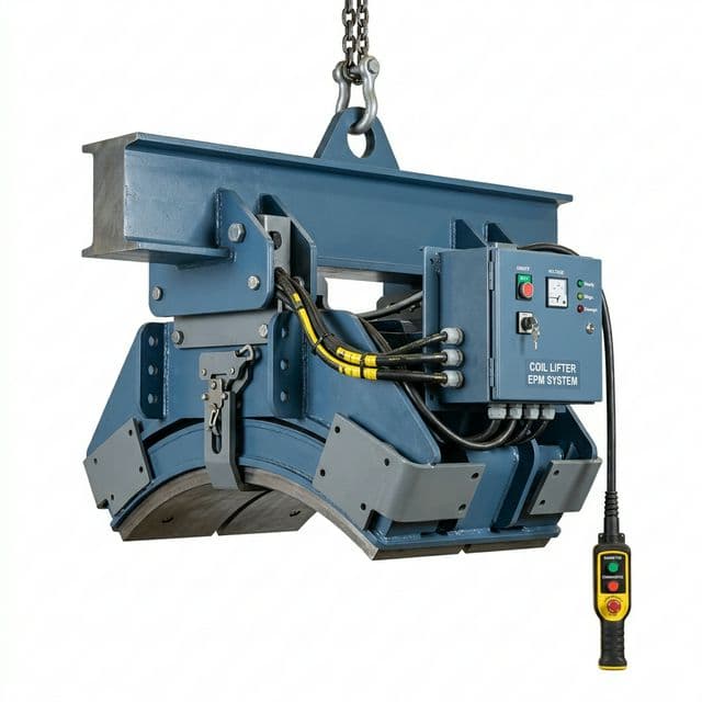
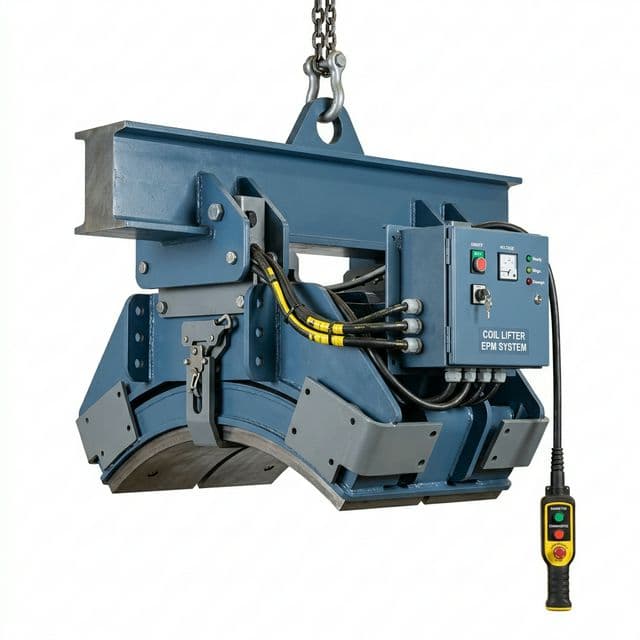
Figure 1. Existing equipment illustration with curved contact shoes. It illustrates a coil-handling arrangement, not a witnessed eye-to-sky lift, a tested capacity, or proof of the internal magnetic circuit.
The Telescoping Mechanism Explained
Telescoping is relative axial displacement of wraps. For an eye-to-sky coil, gravity can move inadequately retained inner wraps downward while other wraps remain attached. Existing stagger, looseness, or transport damage can make the load less predictable. Horizontal coils still need checks against shifting, distortion, rolling, and loss of grip.
A useful screening question is: How is each potentially movable part of the coil supported? Depending on the design, retention may involve direct magnetic attraction at wrap edges and mechanical interaction between wraps. It is incorrect to assume that all inner wraps are held solely by friction, or that a specific pole pattern automatically clamps them securely.
For a hypothetical unsupported portion of mass m, its static weight is m × g. If someone proposes relying on interface friction, a simplified local relationship is friction limit = friction coefficient × normal force. That relationship cannot approve a coil lift: the actual interfaces, force distribution, contact state, and dynamic effects remain unknown. Summing forces across arbitrary wraps can also double-count internal forces. A supplier's analysis must identify the load path and be checked against representative physical tests.
The Inter-Wrap Reluctance Barrier
Flux crossing nonmagnetic gaps encounters more magnetic reluctance than flux traveling through an equivalent steel path. Surface films and gaps therefore matter; oil is not magnetically equivalent to solid steel, even though its relative permeability is close to that of air.
Consider an illustrative geometry calculation, with ID 508 mm, OD 1,500 mm, and strip thickness 1.5 mm. Ignoring coating and winding gaps, the approximate wrap count is (1,500 − 508) / (2 × 1.5), or about 331 wraps. If a hypothetical flux path crossed 330 interfaces, each assigned a 0.025 mm nonmagnetic separation, their arithmetic total would be 8.25 mm.
Those assigned gaps are not measurements of a real coil. The calculation illustrates why many interfaces may matter; it does not predict the actual flux path, holding force, penetration depth, or allowable load. Real magnetic circuits have leakage, parallel paths, and saturation effects that this sum omits.
4. Engineering Solution: Radial Sector Poles vs. Concentric Ring Poles
Alternating radial sectors can create paths along portions of individual wraps instead of forcing all flux across the wound radial build. That makes them a design option worth discussing for annular-face lifting. However, effective coverage, contact, material properties, and test results matter more than the pole-pattern name.
| Pole Shoe Geometry | Potential Use | Question for the Supplier | Engineering Limitation |
|---|---|---|---|
| Radial sector multi-poles | Annular-face coil lifting | How are the innermost and outermost wraps covered across the ID/OD range? | Sector geometry alone cannot establish complete coil retention |
| Concentric ring poles | Annular or solid round workpieces | What coil-specific analysis and tests support the proposed flux path? | A rating on a solid ring cannot be transferred to a wound coil |
| Concave curved shoes | Outside-diameter contact on horizontal coils | Which minimum and maximum ODs achieve the required contact? | Curvature mismatch creates gaps and changes the load path |
| Parallel strip poles | Face contact where geometry is suitable | How does the pattern interact with the actual wrap direction? | Partial coverage needs explicit assessment |
| Articulated or floating segments | Accommodation of documented surface variation | What travel, load sharing, and inspection limits apply? | Compliance cannot make arbitrary edge stagger acceptable |
| Multiple independently controlled zones | A wider coil envelope or selected contact regions | How are active zones confirmed and incorrect selections prevented? | A zone status signal is not itself proof of full-load retention |
A field simulation can explain a proposed circuit, but its assumptions must match the coil and be supported by testing. A colored flux plot is not a load certificate.
5. Coil Operational Envelope & Surface Condition Matrix
The purchasing specification should describe the worst credible incoming condition, not just the easiest sample. Avoid generic percentage derating tables unless the equipment manufacturer has supplied the underlying data for that model and coil family.
| Coil Condition | What Can Change | Required RFQ Input | Acceptance / PO Gate |
|---|---|---|---|
| Cold-rolled oiled strip | Pole separation and inter-wrap slip behavior | Oil/coating description and representative coil condition | Written suitability and representative validation; no assumed friction coefficient |
| Hot-rolled stock with scale | Pole contact and local separation | Scale condition, edge photos, and temperature | Approved preparation and contact criteria for the proposed lifter |
| Stepped or staggered edges | Recessed wraps may have poor contact | Measured maximum step and its location | Manufacturer-defined stagger limit and a rejection rule |
| Loose, damaged, or collapsed coils | Wrap stability and geometry become uncertain | Photos, winding condition, and damage assessment | Quarantine pending a competent handling plan; do not presume another orientation makes magnetic lifting safe |
| Narrow slit coils or bundles | Stability, pole coverage, and retention of individual items | Individual widths, bundle arrangement, and restraint details | Explicit approval for single coils or the complete bundle configuration |
| Electrical steel or coated grades | Magnetic response, coating damage, and residual-field sensitivity | Grade, coating, and downstream process requirements | Agreed surface and residual-field acceptance measurements |
| Hot coils | Magnet performance, insulation, seals, and operator exposure | Maximum contact temperature and exposure duration | Model-specific thermal rating, monitoring, and cooling instructions |
Oil, coating, temperature, and edge steps can interact; multiplying unrelated catalog factors is not a validated coil rating. Ask for one documented operating envelope covering those combined conditions.
If the envelope includes multiple coil families, request a review of the limiting combinations. Include the smallest ID, largest OD, thinnest strip, highest temperature, and worst acceptable surface condition, identifying which combinations actually occur together.
6. Financial Payback & TCO: Comparing C-Hook Replacement Fairly
Magnetic handling can reduce bore contact or positioning work in an appropriate application. It cannot promise zero scrap, zero assistance, or a fixed increase in warehouse capacity. First establish the existing damage mechanism: poorly protected hook contact, impacts, winding defects, and upstream transport damage require different remedies.
Measure several representative shifts before estimating savings. Record complete move times, coil mix, recoverable scrap value, damaged mass attributed to the handling step, maintenance, and actual labor deployment. Include trial and training time in the investment. A faster lift creates cash savings only when the released time has a usable operational or financial value.
A Reproducible, Hypothetical Scrap Calculation
Assume 4,000 relevant transfers per year, a measured reduction that would need to be demonstrated of 10 kg of damaged strip per transfer, and a net loss of $800 per metric ton after scrap recovery. The hypothetical annual saving is:
4,000 × (10 / 1,000) × $800 = $32,000 per year.
If the installed upgrade cost were $80,000 and additional annual operating costs were $4,000, with no other monetized benefits, simple payback would be $80,000 / ($32,000 − $4,000), or about 2.9 years. If the demonstrated damage reduction were only 5 kg, the same arithmetic gives about 6.7 years. These are illustrative inputs, not equipment prices or typical industry returns. Zero demonstrated reduction means this scrap-saving case has not been established.
Build the Full Cost Comparison
| Cost or Benefit | Baseline Measurement | Proposed-System Evidence | Avoid This Error |
|---|---|---|---|
| Installed equipment | Existing replacement or refurbishment cost | Quotation including beam, controls, delivery, and integration | Comparing a bare C-hook with a fully installed magnetic system |
| Handling damage | Attributable damaged mass and net financial loss | Like-for-like trial across representative coils | Assuming all incoming damage disappears |
| Labor | Staff time and actual deployment per transfer | Approved future procedure and observed staffing | Treating released minutes as a full eliminated salary |
| Throughput | Complete route cycle time and bottleneck | Trial covering positioning, switching, travel, and landing | Timing only magnet activation |
| Floor space | Usable layout with access and emergency routes | Reviewed layout including clearances, supports, and floor loading | Treating removal of bore-entry space as permission for zero aisles |
| Power and maintenance | Metered or estimated annual costs with assumptions | Duty profile, service plan, inspections, and consumables | Assuming pulse-only switching makes ownership costs zero |
| Changeover and downtime | Current availability and failure history | Training, spares, commissioning, and recovery plan | Omitting the cost of an interrupted coil bay |
| Residual value and risk | Remaining equipment life and recovery value | Finance-approved assumptions and sensitivity analysis | Counting both time savings and extra output from the same released capacity |
Eye-to-sky storage may change the layout, but storage stability, floor bearing capacity, access, fire protection, and downstream orientation still constrain the result. Show an approved before/after layout and quantify usable positions. Do not adopt a percentage space-saving claim without that comparison.
7. Safety Standards, Interlocks, and Proof Testing (ASME B30.20 & EN 13155)
A global RFQ should name the installation jurisdiction and contractually applicable standard editions. A standard reference is not evidence that a particular product is certified, and compliance in one market does not automatically establish acceptance elsewhere.
ASME B30.20 & ASME BTH-1: Separate Their Roles
ASME describes BTH-1, Design of Below-the-Hook Lifting Devices, as design criteria used with B30.20. B30.20 addresses safety aspects including marking, inspection, testing, maintenance, and operation. The designer must select and document the applicable design category, service class, load cases, and fatigue assumptions; these do not follow from tonnage or the phrase “three-shift operation” alone.
Keep structural design factors, magnetic breakaway force, proof loading, and rated working load distinct. They describe different acceptance questions. Ask the supplier to identify the exact governing clauses, test conditions, and applicability to the supplied coil lifter. Do not impose an internet-derived universal ratio or substitute a dynamic lift for a prescribed test without an approved technical basis.
EN 13155 and the Control Specification
For an installation using EN 13155, have the responsible designer identify the applicable edition and requirements for the magnet type and intended operation. This article does not reproduce or verify specific EN clauses, button spacing, safety coefficients, or control-system performance levels.
The RFQ should ask the supplier to explain:
- How unintended release is prevented, including the operator command sequence and any suspended-load release inhibition.
- What switching confirmation establishes, how incomplete switching is detected, and which faults stop hoisting.
- What happens to magnetic holding, crane brakes, indication, and recovery after a supply failure.
- Which sensors and interlocks are used, their diagnostic limitations, and how the acceptance procedure tests them.
Those questions define review topics; a pulse-current reading alone does not measure retention of every wrap. The HSE guidance also highlights falling-load hazards, load-specific selection, and safe operating arrangements.
Agree the Acceptance Evidence Before Ordering
The test plan should identify lifter serial number, coil geometry and grade, surface and winding condition, temperature, rated load, instrumentation, test method, criteria, and witnesses. Include representative limiting coil configurations and defined responses to faults. The supplier and competent responsible person must specify safe test arrangements; this guide is not an instruction to perform a breakaway test over a warehouse floor.
Reject approval based solely on a pull test against a clean solid plate when the claimed use is an uneven wound coil. Resolve discrepancies before production use and retain the instructions, inspection schedule, and acceptance records with the equipment.
8. The Engineering & Procurement RFQ Checklist
A request saying only “magnet for 20-ton steel coils” leaves the most consequential assumptions open. Use this checklist to make bids comparable:
- 1. Geometry and orientation: Minimum/maximum ID, OD, strip width, and pickup/landing orientation; identify any upending step separately.
- 2. Load and crane capacity: Minimum/maximum coil mass plus the proposed lifter, beam, and accessory masses; check the complete crane arrangement.
- 3. Grade and condition: Exact steel grades, heat treatment, winding condition, and incoming damage criteria. Magnetic response alone does not approve a grade.
- 4. Strip gauge and coil families: Thinnest and thickest strip, single coils versus bundles, and the combinations actually received.
- 5. Surface and oil: Coatings, scale, rust, oil condition, and representative photos or samples.
- 6. Edge stagger and contact: Measured step distribution and supplier-defined limits, inspection method, and rejection procedure.
- 7. Temperature: Maximum surface temperature, exposure time, ambient conditions, and monitoring needs.
- 8. Power and duty: Available supply, interface signals, transfers per hour, travel route, and power-loss recovery requirements.
- 9. Safety and documentation: Installation jurisdiction, specified standard editions, control description, training, and inspection requirements.
- 10. Acceptance and downstream process: Representative test coils, witnessed acceptance criteria, surface damage and residual-field limits, and responsible sign-off.
Add a coil-family drawing or spreadsheet to the RFQ. Ask each bidder to mark exclusions and unresolved inputs explicitly. If a supplier cannot approve a limiting combination, narrow the proposed operating envelope or retain another approved handling method for that stock.
9. Frequently Asked Questions (FAQ)
What causes a steel coil to telescope when lifted vertically?
Wraps telescope when axial forces exceed the retention available to the affected portion of the coil. Poor magnetic contact with inner wraps, winding condition, oil, and existing stagger can contribute. The remedy is a validated load-retention design and defined incoming-coil limits, rather than simply choosing a larger nameplate capacity.
Can an Electro-Permanent Magnet (EPM) drop a coil during a blackout?
An EPM normally retains its magnetic holding state without continuous electrical power after successful switching. A load can still fall through poor contact, slipping wraps, damage, or other failures. Power-loss retention is one feature to verify in the complete lifting system; it is not an unconditional guarantee against a dropped load.
Do radial sector poles always prevent telescoping better than concentric ring poles?
No universal ranking can replace coil-specific validation. Radial sectors can offer favorable paths along wraps, while a proposed concentric arrangement needs evidence for its intended load. Compare actual coverage, contact gaps, material response, and representative retention tests. Neither pattern establishes “100% core grip” by itself.
How much warehouse floor space can switching from C-hooks save?
There is no defensible universal percentage. Removing bore-entry clearance can help some layouts, but inspection access, emergency routes, coil stability, crane coverage, and downstream handling remain. Calculate usable storage positions in an approved layout and include any additional upending or support equipment.
Can an EPM coil lifter handle uneven or stepped edges?
Only within its documented contact and stagger limits. Floating or articulated shoes may accommodate specified variation, but they have finite travel and load-sharing limits. Request acceptance evidence for the worst permitted step; do not infer suitability from a generic millimeter allowance.
Will magnetic handling leave residual magnetism that affects downstream work?
It can. Residual field depends on the steel, magnetic circuit, and switching or demagnetizing process. Agree measurement locations, instrument, limit, and downstream process acceptance with the supplier and process owner. A release pulse does not guarantee a universal gauss value or elimination of welding and swarf problems.
How do oiled coils affect magnetic lifting capacity?
Oil can affect inter-wrap slip and pole separation. Its near-air permeability does not make a film equivalent to steel contact. Use the actual oiled condition in application review and validation; do not assign a universal friction coefficient or capacity-reduction percentage.
Can the same magnetic lifter change a coil from eye-horizontal to eye-to-sky?
Only if it is specifically designed, rated, and validated for the full turning operation. Rotation changes the contact forces and load path. A lifter approved for a stationary orientation is insufficient evidence; a separate rated upender may be needed.
Can magnetic lifters handle aluminum or stainless steel coils?
Aluminum and copper are unsuitable for conventional ferromagnetic lifting. Stainless behavior varies by alloy and processing: ferritic or martensitic grades may be candidates, while austenitic grades are generally unsuitable for this use. Any magnetic response, including response after cold working, still falls short of an approved lifting rating.
What is the typical ROI for replacing a C-hook?
This guide does not claim a typical payback. Use installed cost, demonstrated damage reduction, actual labor value, and maintenance costs from your operation. The hypothetical example above gives about 2.9 years with its stated inputs and about 6.7 years when the assumed damage reduction halves.
Sources & Industry References
Reviewed November 5, 2026. These primary sources support the general safety and design context. They do not establish product certification, coil-specific capacities, or the hypothetical financial inputs above. Public summaries and contents pages do not replace the complete applicable standards.
- UK Health and Safety Executive — Magnetic lifting devices. Guidance on application suitability, falling-load hazards, operating arrangements, inspection, and training. Its regulatory context is the UK; historical standard references on that page should not be treated as current editions for a new project.
- ASME — BTH-1: Design of Below-the-Hook Lifting Devices. Publisher description explaining the design scope and its relationship with B30.20; it does not establish the design classification for this hypothetical application.
- ASME — B30.20-2021 published table of contents. Identifies the standard's scope and separate lifting-magnet chapters. This is an edition-specific contents reference, not a claim that the 2021 edition is the current or contractually applicable one.
Discuss a Magnetic Coil Handling Application with LiftMagnetics
Send the operating envelope before requesting a model or capacity commitment. An application review should identify missing inputs, the proposed handling orientation, and the evidence needed to assess a suitable configuration.
- Submit your coil dimensions, surface condition, and lifting route to discuss application suitability and required documentation.
- Compare our heavy-duty permanent lifters for plate and structural steel when your workpieces are solid sections rather than wound coils.
- Explore the PML series for standard steel plate handling. Those plate-handling ratings do not establish suitability for coils.
Author

More Posts
Buyer RFQ Email Examples (Good vs Bad)
Practical B2B examples showing why some magnetic lifter RFQ emails fail and how to write high-quality inquiry emails that suppliers can quote quickly.

Battery Lifting Electromagnets vs EPMs: Procurement Guide
Compare battery-powered lifting electromagnets vs EPMs for safety, TCO, power-loss behavior, duty-cycle limits, battery upkeep, and RFQ checks before you buy.
EN 13155 vs. ASME B30.20: A Procurement Guide to Lifting Magnet Safety Standards
Compare ASME B30.20 and EN 13155 for lifting magnet procurement, including 3:1 breakaway factors, backup power rules, RFQ checks, and documentation risks.