
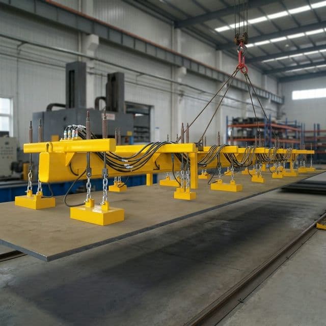
Multi-Magnet Spreader Beams for Long Steel Plates: Deflection Limits, Magnet Spacing, and Rigging Engineering
Compare multi-magnet spreader beams for long steel plates. Review spacing calculations, overhang risks, rigging checks, and the RFQ checklist for your crane.
Why can long steel plates peel away even when summed magnet ratings exceed plate weight? Plate sag and end overhang can rotate the steel away from a pole face, opening an air gap and redistributing load to other modules. Multi-magnet spreader beams for long steel plates must address this flexibility as well as lifting capacity. There is no universal safe magnet spacing or peel angle for every plate and magnet combination.
Last reviewed: November 2, 2026.
Scope: Global engineering and procurement guide for steel service centers, shipyards, fabricators, and crane specifiers considering plates from 6 m to 24 m long. Examples assume a single, horizontal, ferromagnetic steel plate. Contractual lifting codes, crane limits, and regional requirements take precedence.
Limit: Supplier-published selection guidance, not a certified lifting design. Calculations below are illustrative elastic-strip calculations, not physical test results or approved load charts. A qualified engineer and the equipment manufacturer must verify the actual plate envelope, suspension, magnet ratings, and lift plan.
Planning a crane retrofit or preparing an RFQ? Submit your plate envelope and crane parameters for an application review using the procurement checklist below.
1. The Physics of Plate Sag and the Peeling Failure Mode
A breakaway-force result describes a specified pull-test arrangement; it cannot establish safe lifting capacity for every flexible plate. In a multi-magnet system, the reaction at each module depends on plate stiffness, support positions, beam deflection, suspension travel, and center of gravity. Adding nameplate capacities does not prove that every module remains within its application-specific working load limit (WLL).
HSE's magnetic lifting guidance identifies flexible-load droop and overhang as peel-off risks and advises considering magnet coverage as well as lifting ability.
Conceptual schematic, not to scale. Articulation can reduce angular mismatch but cannot flatten a curved plate or establish an allowable air gap.
The Cleavage (Peel) Stress Concentration
- Rotation changes contact: Plate bending can lift one pole edge while the opposite edge remains in contact. Local plate curvature matters even when a module can pivot.
- Air gap changes attraction: Obtain the selected module's tested capacity curves for thickness, alloy, temperature, and surface condition. Neither a fixed percentage loss at 0.3 mm nor an inverse-square law is a general lifting-magnet rating rule.
- Load redistribution matters: If one module loses contact, remaining modules can become overloaded. Springs and gimbals alone do not establish redundancy.
The acceptance criteria must specify allowable plate deflection, local slope, contact gap, module reaction, and suspension travel. A structural beam's serviceability ratio such as span/400 does not by itself establish a magnetic-contact limit.
2. Magnet Spacing and Cantilever Overhang Calculations
Start with the thinnest and longest plate combinations actually handled. Separately check the heaviest plate for magnet capacity, structural strength, and crane capacity; the governing cases can differ.
A Reproducible Elastic-Strip Screening Model
For a uniformly loaded, simply supported span, the Euler–Bernoulli beam equations are:
w = rho × b × t × g                  distributed self-weight, N/m
I = b × t³ / 12                      second moment of area, m⁴
delta_mid = 5 × w × S⁴ / (384 × E × I)
theta_support = w × S³ / (24 × E × I)  radians
Here, S is support pitch in meters, b is strip width in meters, t is thickness in meters, and E is elastic modulus in pascals. Use rho = 7,850 kg/m³, g = 9.81 m/s², and E = 210 GPa for the illustrative calculations below. These are stated material assumptions, not measurements of a supplied plate.
Model boundary: This is a one-dimensional, small-slope, linear-elastic strip with ideal simple supports and gravity loading only. Real plates are continuous across several discrete magnet footprints. Overhang moments, transverse bending, residual curvature, uneven supports, finite pole width, and crane dynamics need a model of the actual assembly; the simple-span result is not a guaranteed conservative bound.
Substituting w and I cancels width in this strip model: deflection scales as S⁴/t² and support slope as S³/t². Halving thickness quadruples deflection at unchanged pitch. Reducing pitch by about 29% restores the original absolute deflection, but does not necessarily restore the original slope or contact condition. Width still matters for total load and transverse plate behavior.
Illustrative Thickness Sensitivity Table — Not a Spacing Chart
All six rows use S = 1.000 m with the assumptions above. Values are rounded; they are calculated, not tested. No row approves a magnet count, overhang, or lift.
| Plate thickness | Trial pitch S | Calculated mid-span sag | Calculated support slope | Engineering decision still needed |
|---|---|---|---|---|
| 4 mm | 1.000 m | 3.581 mm | 0.657° | Check thin-plate capacity, curvature, and single-sheet pickup |
| 6 mm | 1.000 m | 1.592 mm | 0.292° | Check local contact and suspension alignment |
| 8 mm | 1.000 m | 0.895 mm | 0.164° | Check finite pole footprint and surface gap |
| 12 mm | 1.000 m | 0.398 mm | 0.073° | Check unequal reactions across the complete support layout |
| 20 mm | 1.000 m | 0.143 mm | 0.026° | Check module capacity and total hook load |
| 35 mm | 1.000 m | 0.047 mm | 0.009° | Check maximum plate mass, beam strength, and crane limits |
Worked check: For a 6 mm strip at 1 m pitch, w/(E×I) = 0.12224 m⁻³, giving 1.592 mm sag and 0.292° support slope. Doubling the pitch to 2 m multiplies these by 16 and 8 respectively: approximately 25.47 mm and 2.335°. Those results illustrate sensitivity; they do not define an allowable slope. Reassess linear-model assumptions if the predicted deformation becomes large.
Cantilever Overhang and Support-Count Geometry
A uniformly loaded cantilever with a fixed, nonrotating root has delta_tip = w × Lo⁴ / (8 × E × I). An outer magnet is not a fixed clamp: rotation at its support adds end displacement, and the overhang moment changes adjacent support reactions. Model the overhang together with the supported plate; do not prescribe a universal Lo ≤ 0.35S or a universal meter limit.
For equally spaced longitudinal support stations with equal end overhangs, geometry gives L = 2Lo + (n − 1)S. A 12 m plate, a trial 0.5 m overhang at each end, and 1 m pitch imply 12 longitudinal support stations. This is geometry only. Each station may require more than one magnet across the width, and every station's reaction and contact must be verified.
For scale, a single 12 m × 2 m × 6 mm plate at the assumed density weighs 1,130.4 kg. The crane must also carry magnets, beam, controller, and rigging. Dividing plate weight by the number of modules does not establish the maximum reaction of any module.
3. Structural Spreader Beam Configurations
The beam layout must accommodate plate length, width, center of gravity, available hook height, and the load path through the upper rigging. A lifting beam carrying bending and a sling-supported spreader carrying compression require different structural checks; the product label alone does not define the load path.
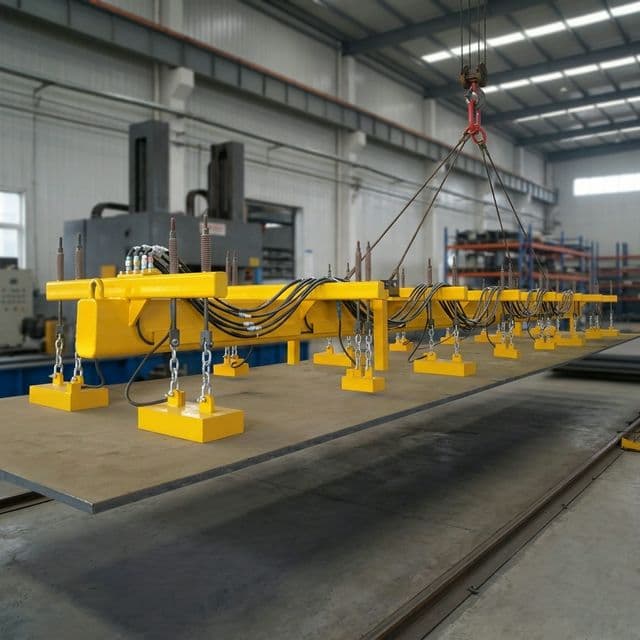
Product illustration from the site catalog; it does not document a witnessed load test, a specific installation, or an approved capacity.
Spreader Architecture Selection Matrix
| Beam configuration | Best-fit handling need | Adjustment approach | Procurement checks | Limitation to resolve |
|---|---|---|---|---|
| Fixed box-girder | Repeated stock lengths | Fixed stations or approved pin positions | Beam strength, fatigue duty, module reactions | Short plates may not cover all stations |
| Telescopic spreader | Several plate lengths | Mechanically or power-adjusted arms | WLL at each extension, locks, cable travel | Extended position changes stiffness and reactions |
| H-frame cross-beam | Plate needing transverse support | Two or more longitudinal rows | Crosswise bending and row load sharing | Width alone does not determine row count |
| Low-headroom lifting beam | Restricted hook height | Direct top attachment | Bending strength, lifting lugs, clearance | Reduced headroom can change tare and load path |
| Articulated tandem assembly | Very long plates | Linked beams and engineered equalizer | Complete load path and stability | Equalization must be demonstrated, not assumed |
| Dual-use forklift/crane attachment | Handling by different machines | Approved fork pockets and lifting attachment | Separate machine ratings and retention | Crane approval does not establish forklift capacity |
Rigging check: For two symmetric upper sling legs at angle alpha above horizontal, ideal static leg tension is T = W_total / (2 × sin(alpha)), where W_total includes the suspended assembly and plate weight as a force. At 30°, each leg carries a tension equal to the total suspended weight. This simplified relation excludes unequal loading and dynamics; verify sling angles, attachments, and crane limits for the actual arrangement.
4. Suspension Mechanics: Articulated Gimbal Mounts vs. Rigid Bolting
A rigid mount can leave some magnets above a wavy plate or impose an angular mismatch as the beam and plate deflect. Articulation can help each module follow the local surface, provided the travel, restraints, and attachment strength suit the design.
- Gimbals or spherical joints: Specify the required pitch/roll range and mechanical stops from the predicted local plate slope. A nominal ±5° range, if offered, is a product parameter, not a universal requirement or guarantee of full contact.
- Spring suspensions: Specify preload, stiffness, available stroke, and mechanical retention. They can accommodate height variation, but different spring compression can create unequal reactions. Include that behavior in the load-sharing analysis.
- Chain or swivel hangers: Check length, alignment, permitted rotation, and snagging. Hangers must not introduce side loads outside the module's rating.
At the factory acceptance test (FAT), request evidence of contact and individual module loading at the worst specified plate camber and relevant beam extensions. A total lifted mass alone does not demonstrate acceptable load sharing.
5. Electrical Architecture & Safety Control: EPM vs. Electromagnet Systems
Power architecture changes the failure response, but does not remove plate-contact or rigging requirements. Electro-permanent magnets (EPM) use a pulse to switch magnetic state and permanent magnetism to hold the load; continuously powered electromagnets need holding current. Pulse duration, materials, switching energy, and temperature limits depend on the selected product.
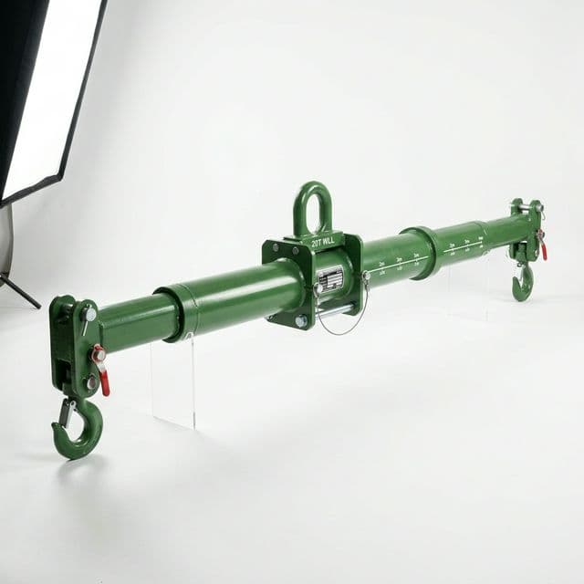
Telescopic mechanical beam illustration. It does not show an EPM assembly or verify a magnetic system's rating.
Power and Safety Control Comparison
| Architecture feature | Externally powered DC electromagnets | Battery-fed electromagnets | Electro-permanent magnets |
|---|---|---|---|
| Holding energy | Continuous current required | Continuous current from battery | No continuous excitation current after successful switching |
| Supply interruption | Engineered backup or retention strategy needed | Remaining charge and circuit integrity matter | Power loss alone does not switch off an engaged module |
| Duty and temperature | Confirm coil heating and duty rating | Confirm coil duty and battery endurance | Confirm magnet, workpiece, and controller temperature limits |
| Cabling | Size for continuous current and movement | Inspect local wiring and charging circuit | Size switching circuit for its peak current, not just control signals |
| Release and residual field | Verify release procedure and residual field | Verify release capability at low charge | Verify demagnetization sequence and residual field; results vary |
| Acceptance evidence | Backup operation, warnings, contact and capacity tests | Battery health, warnings, contact and capacity tests | Switching-state verification, contact and capacity tests |
An EPM's power-loss behavior does not guarantee indefinite safe suspension, immunity to peeling, or safe operation after mechanical damage. Do not leave a load suspended unattended. The risk assessment must cover unintended release commands, incomplete switching, temperature, and loss of pole contact. HSE distinguishes permanent/EPM power-loss behavior from powered magnets; its older guidance is not a substitute for the current contractual standard.
Multi-Zone Group Switching for Different Plate Lengths
Short plates may leave outer modules uncovered. The supplier should define an approved layout for each plate family, identifying active stations, covered pole faces, permitted center-of-gravity range, and resulting module reactions. Zone names such as center pair, inner group, and full beam are control labels; they do not imply fixed allowable plate lengths.
Validate plate detection, zone selection, unused-module behavior, and the response to a failed sensor. Reduced-flux pickup or sheet separation must follow a validated procedure; a partial pulse cannot guarantee pickup of exactly one sheet at any gauge.
Request a configuration review with your plate matrix and cycle requirements. The magnetic lifting product catalog is a starting point for discussing available equipment.
6. ASME B30.20 & EN 13155: Standards, Interlocks, and Testing
State the required standard and edition in the RFQ. ASME B30.20 covers below-the-hook lifting devices; ASME BTH-1 addresses their design. EN 13155 addresses non-fixed load lifting attachments. The applicable provisions depend on the device type, intended duty, jurisdiction, and contract. These references are not interchangeable approvals.
Release Prevention and State Verification
Ask the supplier to document protection against inadvertent release, the conditions allowing demagnetization, and the response to a failed control. Dual control actions and landing/load-state interlocks are possible measures; do not infer a universal two-second hold time or an exact clause without the applicable standard text.
Current-pulse monitoring and flux sensors can provide useful status information, but neither alone measures safe holding capacity in every condition. Define sensor limits, fault behavior, and any hoist permissive in the agreed control design.
Separate Structural Proof and Magnetic Holding Evidence
- Structural design: Request the complete load cases, beam and attachment checks, fatigue/service assumptions, suspension reactions, and the basis for the design factors.
- Structural proof test: Agree the test coefficient, setup, sequence, and acceptance criteria under the applicable edition. Do not apply a generic 125% or 150% coefficient to every complete magnetic assembly.
- Magnetic test: Require the test plate alloy, thickness, flatness, surface/gap, temperature, pull direction, and state of the magnet to be recorded. A breakaway-to-WLL ratio is conditional on those details and the magnet type; it is distinct from structural proof loading.
- Marking and instructions: Request rated configurations, assembly tare, minimum plate thickness, allowed surfaces and temperatures, identification, operating instructions, and inspection requirements. Confirm how these limits are marked or supplied.
The BSI EN 13155 catalogue entry identifies the standard's scope. Obtain the governing text before assigning coefficients or claiming compliance. HSE's lifting-equipment overview provides UK context; local obligations must be checked for other markets.
7. The Procurement & Rigging Engineering RFQ Checklist
A quote for a “10-ton magnetic spreader” is incomplete without the operating envelope. Supply these ten items and request a configuration-specific response:
- 1. Plate dimensional matrix: Minimum, nominal, and maximum length, width, and thickness, including combinations actually lifted and the thinnest long plate.
- 2. Metallurgy and grades: Identify each steel grade and whether nonmagnetic or weakly magnetic stock is present. Do not assume all stainless steel is suitable.
- 3. Temperature: Give maximum plate and ambient temperatures, contact duration, and cycles. Hot work needs a system explicitly rated for that service.
- 4. Surface condition: State scale, rust, roughness, coatings, contamination, and expected effective air gaps.
- 5. Flatness and load shape: Give camber, waviness, cutouts, remnant shapes, and center-of-gravity variation; identify single-sheet versus stack pickup.
- 6. Crane and rigging: Provide permissible hook load, headroom, hoist speed/acceleration, upper sling geometry, and attachment constraints; include all equipment tare.
- 7. Beam layout: Request pitch, end overhang, row spacing, active-zone maps, extension limits, and the worst individual module reactions for every plate family.
- 8. Electrical interface: Provide voltage, available peak/continuous power, cable travel, remote-control requirements, and crane/PLC interfaces.
- 9. Controls and operating plan: Request release protection, switching-state verification, sensor fault response, power-loss behavior, single-sheet procedure, and exclusion-zone arrangements.
- 10. Standards and acceptance: Specify jurisdiction, standards/editions, design evidence, agreed structural and magnetic FAT procedures, marking, manuals, and inspection plan.
8. Frequently Asked Questions (FAQ)
Can I lift a 16-meter plate using only two high-capacity lifting magnets?
Length and summed magnet ratings cannot answer this. A sufficiently stiff plate and an approved two-point arrangement may be feasible, while a thin plate may need many more support stations. Verify span, end overhang, transverse bending, local contact, and each module reaction. There is no universal mandatory module count for all 16 m plates.
What is the maximum cantilever overhang past the outer magnets?
Use the approved layout for the plate and lifter combination. Overhang affects end droop, support rotation, and reactions in neighboring spans. Neither 35% of pitch nor a fixed meter limit is established here as a standard requirement. Request an overhang calculation and contact assessment for the worst plate.
Why use articulated mounts instead of rigidly attaching magnets to the beam?
Articulation can help a module follow local plate slope and accommodate height variation. It still needs adequate travel, retention, and verified reactions. It cannot remove local plate curvature or compensate for scale and coatings, and spring packs do not automatically equalize loads.
Are EPM spreaders safer than continuously powered electromagnets?
EPM avoids the need for continuous excitation power to retain its switched-on magnetic state. That is a useful power-loss advantage, but system safety still depends on contact, temperature, load sharing, release controls, and operating procedure. Compare complete systems and their failure responses, not only magnet technology.
How does plate thickness affect magnet spacing?
In the stated elastic-strip model, self-weight deflection scales as S⁴/t². A 6 mm plate therefore deflects four times as much as a 12 mm plate at the same pitch. Convert that sensitivity into a layout only after defining allowable contact, slope, reactions, and magnetic thickness ratings for the actual system.
How do I avoid picking up two thin plates from a stack?
Ask for a validated single-sheet procedure and detection method for your plate thickness, surface, and stack condition. Reduced-flux pickup, separators, or mechanical aids may help, but flux adjustment alone is not proof of single-sheet pickup. Any shedding step must keep unintended sheets within a controlled landing area before travel.
What safety factor applies to the beam and the magnets?
Specify it separately for structural design, structural proof loading, and magnetic breakaway/WLL under the applicable standard edition and device classification. A generic 3:1 statement cannot establish compliance for all three. Require the supplier to identify test conditions and demonstrate that each module's maximum reaction stays within its applicable rating.
When does a wide plate need two rows of magnets?
When transverse bending, contact, or stability checks show one row is insufficient. Plate width, thickness, pole footprint, row spacing, and stiffness all matter; 2.5 m is not a universal cutoff. Ask the engineer to compare inline and H-frame layouts for the actual plate envelope.
Sources & Industry References
Reviewed November 2, 2026. These sources support risk assessment and standard selection, not the illustrative table as an approved load chart. Equations and numerical examples above state their own assumptions; no physical tests or customer outcomes are claimed.
- UK Health and Safety Executive — Magnetic lifting devices. Guidance on magnetic lifting hazards and application-specific selection. Its standards references include older editions; use it for risk context, not current clause-by-clause compliance.
- British Standards Institution — EN 13155 catalogue: Crane safety — Non-fixed load lifting attachments. Official catalogue scope; obtain the applicable full standard and edition for detailed design and testing requirements.
- UK Health and Safety Executive — Safe lifting by machine. UK lifting-equipment overview. It is not an international certification or a plate-spacing specification.
Engineer Your Multi-Magnet Spreader Solution with LiftMagnetics
For an application discussion, send your plate matrix, crane limits, surface condition, and required cycle rate. Request a proposed layout with assumptions, rated configurations, and an acceptance-test plan before selecting a system.
- Contact LiftMagnetics for an application review.
- Review heavy-duty magnetic lifters for capacity discussions; this range does not itself specify a complete EPM spreader system.
- Browse the magnetic lifting product catalog to discuss equipment options.
More Posts

Lifting Magnet Derating Factors: How Air Gaps, Surface Roughness, and Material Thickness Impact Real-World Capacity
Lifting magnet derating guide for air gaps, roughness, steel thickness, and alloys. Use RFQ checks, source-backed limits, and contact engineering today.


Battery Lifting Electromagnets vs EPMs: Procurement Guide
Compare battery-powered lifting electromagnets vs EPMs for safety, TCO, power-loss behavior, duty-cycle limits, battery upkeep, and RFQ checks before you buy.

Safety Factor vs Breakaway Force Checklist
A procurement-focused checklist to evaluate magnetic lifter safety claims using both safety-factor framing and breakaway-force considerations, with test matrix and PO gates.