
Residual Magnetism After Magnetic Lifting: Managing Welding Arc Blow, Gauss Limits, and Demagnetization Protocols
Manage residual magnetism after magnetic lifting: assess welding arc blow, agree Gauss limits, and use a demagnetization checklist for your next equipment RFQ.
Can residual magnetism after magnetic lifting cause welding arc blow? Yes. Magnetic handling can leave steel magnetized after release, and this residual field can deflect a welding arc. The practical response is to measure the prepared joint, agree a process-specific acceptance limit, and demonstrate a suitable demagnetization method on representative material. Turning a lifter OFF does not demonstrate that the workpiece is ready to weld.
For fabrication managers, welding engineers, and equipment procurement teams, the decision is how to control remanence across the handling-to-fabrication workflow.
Last reviewed: October 29, 2026.
Scope: Global, English-language engineering and procurement guide for ferromagnetic steel fabrication, pressure vessels, shipyard panels, pipe fabrication, and machining cells. Contractual standards, their editions, and the applicable welding procedure specification (WPS) take precedence.
Limit: This is supplier-published application guidance. It reports no measured product performance or customer trials. The tables are decision aids, not universal Gauss limits or a qualified welding/NDT procedure. Material condition, geometry, field direction, probe position, and welding parameters affect the result.
Planning an equipment purchase or resolving shop-floor arc blow? Submit your material and welding specifications for an application review, using the procurement checklist below.
1. Executive Summary & Core Engineering Principles
A lifting magnet establishes a magnetic circuit through a suitable steel workpiece. Some magnetization can remain after that circuit is released. TWI's explanation of magnetic arc blow identifies magnetic handling and current-return placement among the causes of arc deflection and lack of fusion.
- Release and demagnetization are separate functions: A manual permanent magnetic lifter (PML) redirects flux to release a supported load. It is not a controlled workpiece-demagnetization process.
- Arc blow has several causes: Residual magnetism is one possible contributor. Investigate the welding current return and joint geometry as well as the handling history before blaming the lifter.
- A Gauss reading needs context: There is no single field value in this guide that qualifies every weld, machining operation, or magnetic particle examination. Agree the measurement method and acceptance criterion with the responsible engineer.
- Grade alone cannot predict residual field: Heat treatment, prior magnetization, stress, thickness, and part geometry matter. Waiting after release is not a demonstrated demagnetization method.
- Buy verified process capability: An electro-permanent magnet (EPM) may offer an optional demagnetization sequence. Require evidence for the offered model and workpiece; a dedicated demagnetizer may still be needed.
2. Downstream Impact: Setting Gauss Limits by Process
Magnetic flux density can be reported in gauss (G) or millitesla (mT): 1 mT = 10 G. A reading at the plate center cannot substitute for a reading at the actual weld preparation. Fields can change when two parts are brought together for fit-up.
Use the following matrix to decide what to qualify. It deliberately avoids unsupported numerical pass/fail bands:
| Manufacturing operation | Where to assess residual field | What the trial should establish | Acceptance owner | Decision if the trial fails |
|---|---|---|---|---|
| GTAW / TIG root pass | Both bevels and root gap in representative fit-up | Stable arc and acceptable root under the intended WPS | Welding engineer / contract inspector | Demagnetize and repeat field mapping and weld trial |
| Robotic GMAW / MIG | Seam start, middle, end, and repeatable fixture positions | Stable tracking and acceptable bead over the production sequence | Welding and automation engineers | Qualify demag or adjust the approved process |
| SMAW / FCAW | Joint ends, corners, and current-return locations | Arc control and acceptable fusion at the specified current and polarity | Welding engineer | Assess current-return routing and demagnetization |
| Submerged arc welding (SAW) | Root gap and seam ends in assembled condition | Acceptable fusion and bead placement using production parameters | Welding engineer / QA | Review return path, demag, and procedure limits |
| Precision milling / boring | Functional surfaces, edges, and chip accumulation areas | Acceptable chip evacuation and finish | Manufacturing engineer | Trial local or whole-part demagnetization |
| Surface / cylindrical grinding | Machining surfaces before final finishing | Acceptable swarf removal and finish | Manufacturing engineer / QA | Establish a verified pre-grinding demag step |
| Magnetic particle testing (MT / MPI) | Points and orientations required by the examination procedure | Required field condition during testing and residual condition after testing | Responsible NDT authority | Follow the governing procedure for demag and retest |
Writing a numerical requirement: If a buyer proposes 3 G (0.3 mT), record it as a proposed contractual target until the welding/NDT authority approves it. State whether it applies to the maximum absolute reading at defined locations and probe orientations, and how instrument uncertainty is handled. This example is not an ASME, API, ASTM, or universal welding limit. A low reading alone does not qualify weld quality.
A repeatable residual-field measurement and acceptance protocol
- Identify the part: Record grade, heat treatment, dimensions, handling history, joint preparation, and intended downstream process.
- Define the instrument: Use a calibrated field meter appropriate to the expected range. Record meter/probe identification, calibration status, zero/background check, and units.
- Define the geometry: Mark measurement locations at the pole-contact areas, cut edges, corners, bevels, and joint ends. Record probe orientation and distance from the surface; follow the instrument instructions for contact measurements.
- Measure the production condition: Record the field after release and again in representative fit-up, with welding current off. Rotate a single-axis probe through the agreed orientations, retaining the largest absolute reading and its location rather than a convenient average.
- Demagnetize and remeasure: Use the same points, orientations, and instrument after the selected cycle. Record settings, part orientation, number of passes, elapsed time, and the largest remaining reading.
- Qualify the handoff: Run the approved welding or manufacturing trial, retain inspection results, and obtain the responsible authority's acceptance. Check the condition after subsequent magnetic handling or MT if it could remagnetize the part.
A useful acceptance record contains: part ID; measurement map; meter/probe ID; background check; before/after readings with units and orientation; demag settings; cycle time; applicable criterion and revision; trial result; and approver. These are proposed record fields, not test results from LiftMagnetics.
3. The Physics of Residual Magnetism: Remanence vs. Coercivity
Magnetization follows a hysteresis path: removing the applied field does not necessarily return the material to its initial condition. Remanence describes retained magnetization; coercivity describes resistance to its reversal. A surface stray-field reading is not a direct measurement of the material's intrinsic remanent flux density.
Magnetic loading during the lift
Rated lifting capacity does not establish a universal contact flux density or prove that the entire plate reaches saturation. Pole area, air gaps, thickness, material properties, and load geometry all matter. Breakaway verification and lifting safety requirements must follow the equipment instructions and the applicable standard; they cannot be derived from a tonnage-only example.
Material condition matters more than a grade-only prediction
The table identifies trial variables rather than assigning unverified coercivity values or expected Gauss readings to named grades:
| Steel family / examples | Condition to identify | Why it matters to the trial | Demagnetization question |
|---|---|---|---|
| Mild structural steel: A36, S235JR | Hot-rolled, formed, or stress-affected regions | Prior processing and geometry can change the measured pattern | Can the proposed cycle meet the criterion at every mapped location? |
| Structural steel: S355J2, S460QL | Exact grade and delivery condition | These grades must not be assumed to share one microstructure | Has the supplier tested the actual thickness and condition? |
| Wear / high-strength plate: Hardox 450, Strenx 700 | Product designation and heat treatment | Preserve the material's specified properties during remediation | Can ambient-temperature demag meet the requirement? |
| Machinery steel: 4140, 4340 | Annealed versus hardened and tempered | Condition can change response to magnetization and reversal | Is local treatment adequate for the functional surfaces? |
| Creep-resistant steel: P91, P22 | Exact alloy and heat-treatment condition | These alloys have different compositions and must be assessed separately | Can the fitted joint pass the field check and qualified root trial? |
| Tool steel: D2, O1, H13 | Annealed versus hardened condition | A cycle qualified on mild plate may not transfer to hardened tooling | What field strength, frequency, and exposure does the trial require? |
| Austenitic stainless: 304, 316L | Cold work, welds, and actual magnetic response | Austenitic products may show local magnetic response; grade alone cannot establish liftability | If magnetic holding is uncertain, select another validated handling method |
4. Visual Guide: Arc Deflection and a Decaying Demagnetization Waveform
The left panel is a conceptual view of arc deflection, with magnetic field out of the page and conventional current downward. The right panel shows a decreasing alternating drive current. It illustrates a demagnetization principle, not an offered EPM controller specification, measured field, guaranteed residual level, or cycle time. Maurer Magnetic describes controlled, decreasing field reversals for its own demagnetization technology; that does not establish the performance of a lifting magnet.
5. Equipment Comparison: Verify Residual Flux Separately from Release
Compare the proposed hardware and documented options. Technology labels alone do not establish a residual-field ranking:
| Equipment option | Release / operating principle | What can be inferred about residual field? | Evidence to request | Application boundary |
|---|---|---|---|---|
| Manual permanent lifter (PML) | Mechanically redirects the magnetic circuit | OFF does not verify workpiece demagnetization | Before/after field map on representative loads | A separate demag step may be needed before welding |
| DC electromagnet | Powered holding field with a controlled release circuit | Power removal or a release pulse is not proof of low residual field | Controller sequence and load tests | Assess power-loss protection and release behavior separately |
| Battery-powered lifting magnet | Battery supplies an electromagnetic or switching circuit | Battery power says nothing by itself about demag capability | Actual magnetic architecture and supported demag options | Include battery condition and duty limits in the trial |
| Standard EPM | Electrical switching changes a permanent-magnet circuit | Electrical release does not establish whole-part demagnetization | Offered model's release sequence and measured residuals | Do not assume auto-demag is included |
| EPM with documented demag option | Supplier-specific alternating/decreasing sequence | Performance depends on controller and workpiece | Worst-case field map, cycle time, interlocks, and acceptance trial | Residual field remote from pole contacts must also be checked |
| Dedicated tunnel / table / local demagnetizer | Separate field exposure and controlled decay or withdrawal | Capability must be demonstrated for the part and target | Coverage, penetration, orientation, duty, and repeatability | Adds a process station or local treatment step |
Use the magnetic lifter product range to shortlist handling equipment, then ask for a documented demagnetization capability review with the measurement map above.
6. Industrial Demagnetization Protocols: Equipment & Shop-Floor Methods
Demagnetization generally uses field reversals of decreasing amplitude. The required field exposure depends on the workpiece and equipment. Abruptly stopping a strong field can leave the part magnetized.
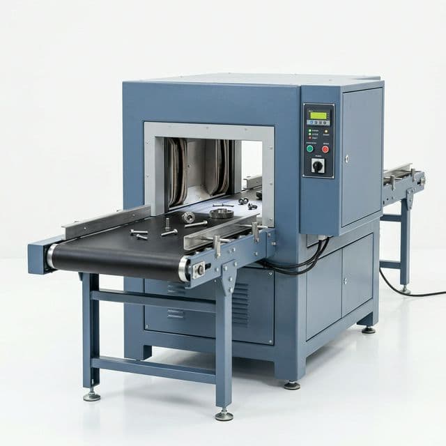
Illustrative equipment image; it is not a photograph of an acceptance test or evidence of a specified residual-field result.
Method 1: An integrated EPM demagnetization option
Where the offered controller supports workpiece demagnetization, ask the supplier to document the release sequence and its validated load envelope. Support the load securely before release or demagnetization, following the equipment instructions. Confirm that the controls prevent inadvertent loss of holding force during a suspended lift.
Measure residual field beyond the contact footprint as well as at the poles. Record the complete supported-release-to-clearance time during the acceptance trial. Neither a sub-second cycle nor zero effect on throughput can be assumed from the EPM label.
Method 2: Conveyor, tunnel, or table demagnetizers
For repeat production, a separate station can provide a controlled treatment independent of the crane's release circuit. Ask the equipment supplier to qualify part position, coil clearance, treatment frequency, field strength, travel speed or exposure time, and field decay/withdrawal sequence. Large sections and complex assemblies need representative trials to establish adequate treatment throughout the required regions.
Method 3: Local yokes or engineered cable-coil systems
Local equipment may be practical for an already assembled joint. A cable-coil setup requires an engineered procedure specifying the approved source, current control, cable insulation and thermal limits, coil arrangement, and termination of the decreasing field. A generic turn count and amperage recipe cannot cover arbitrary steel sections or welding power sources. Select settings with the equipment supplier and responsible site engineer, then verify the result at the joint.
Method 4: Welding-process countermeasures
TWI notes that current-return positioning and, for manual metal arc welding, AC instead of DC can reduce arc blow. Any process change must remain within the approved WPS or be reviewed by the welding engineer. Two return clamps do not guarantee equal currents or cancellation. If field-related instability remains, demagnetize and repeat the acceptance trial before continuing production.
7. The Procurement & Engineering RFQ Checklist
Tonnage and plate dimensions alone do not describe a weld-ready handling process. Include these items in the RFQ and acceptance plan:
- Downstream process: Identify welding process, current/polarity, joint type, WPS, machining operation, or NDT procedure.
- Residual-field criterion: Name the approving authority and applicable contractual clause, or agree a trial-derived criterion. Specify units, maximum/average treatment, probe orientation, measurement distance, locations, and instrument uncertainty.
- Material and geometry: Provide exact grades, delivery/heat-treatment condition, thickness range, dimensions, cut edges, and representative worst-case fit-up.
- Offered capability: Require the exact model, release sequence, demagnetization option, and limitations. Distinguish release assistance from workpiece demagnetization.
- Cycle time and duty: Request demonstrated treatment and total handling times, duty limits, repeat passes, and throughput assumptions.
- Verification record: Agree calibrated instrument/probe, marked measurement map, before/after readings, production trial, inspection evidence, and acceptance sign-off.
- Auxiliary equipment: Define who supplies a separate demagnetizer if the integrated option fails the agreed criterion, including access and part coverage.
- Lift safety: Confirm safe supported-load release, prevention of inadvertent demag while suspended, and applicable lifting-standard requirements with the equipment supplier.
8. Frequently Asked Questions (FAQ)
Does turning a manual permanent magnet lifter OFF demagnetize the steel?
It releases the holding circuit; it does not demonstrate a demagnetized workpiece. Measure the residual field at the locations relevant to the next operation rather than inferring it from the handle position.
What Gauss limit should I specify before welding?
Use the governing contract or an acceptance limit agreed by the welding authority and demonstrated with the intended WPS and fit-up. The 3 G example above is a proposed buyer target, not a universal code requirement. Specify the instrument, locations, orientations, and decision rule alongside the number.
Does retained magnetism mean the steel has been metallurgically damaged?
A residual-field reading alone does not demonstrate a change in grade or mechanical properties. Investigate the actual manufacturing history separately. Heating as a demagnetization shortcut can affect material properties and requires metallurgical review.
Why should I measure joint ends, corners, and the assembled gap?
Geometry and current-return routing can create a different field pattern from the flat plate center. Measure the intended welding condition; a center-surface reading alone may miss the location where arc instability occurs.
Do EPM lifters always leave less residual magnetism than PMLs?
No universal ranking is justified. Some controllers offer a workpiece-demagnetization option, but actual performance depends on the model, cycle, and load. Compare recorded field maps and production trials rather than the equipment label.
Can heating replace electromagnetic demagnetization?
Heating can alter a steel's magnetic state, but it can also change its heat treatment, dimensions, and surface condition. Do not prescribe a generic heating temperature for finished structural or pressure-retaining parts. Evaluate an ambient-temperature demagnetization method with the responsible engineer first.
Does demagnetization add cycle time?
It can. Include supported release, treatment, any separate transfer, repeated passes, measurement, and clearance in the process study. Require a measured time for the proposed load and acceptance criterion; no fixed duration or zero-throughput-impact claim is made here.
Sources & Industry References
Reviewed October 29, 2026. These references support the stated mechanisms and document types; they do not establish universal numerical acceptance bands. The measurement protocol, comparison tables, and RFQ checklist above are LiftMagnetics' proposed application framework, not first-party test evidence.
- TWI — What is magnetic arc blow?. Technical explanation of arc deflection associated with magnetic handling and welding-current return paths, with mitigation context. It does not supply universal process-by-process Gauss limits.
- Maurer Magnetic AG — Maurer Degaussing method. Manufacturer's German-language explanation of controlled decreasing field reversals. It describes that supplier's technology and is not evidence of LiftMagnetics EPM performance.
- ASTM International — ASTM E709-21: Standard Guide for Magnetic Particle Testing. Publisher record for the magnetic particle testing guide. The full text is access-restricted and was not verified for this guide. Consult the contractually applicable edition and responsible NDT authority. No numerical acceptance limit is attributed to this source here.
Specify a Verifiable Magnetic Handling Process with LiftMagnetics
Define the downstream requirement before choosing the handling and demagnetization arrangement. A useful inquiry includes steel grades and conditions, part dimensions, joint preparation, the applicable WPS or inspection procedure, and your field-measurement plan.
- Contact our team for an application review and request documented capabilities and a representative acceptance trial for any proposed demagnetization option.
- Explore our heavy-duty permanent magnetic lifters for plate handling, with downstream demagnetization assessed separately.
- Compare the published magnetic lifter product categories before preparing your RFQ.
More Posts

Temperature Limits of Lifting Magnets: A Buyer’s Guide to Handling Hot Steel
Buyer’s guide to lifting magnet temperature limits for hot steel. Compare permanent, EPM, and electromagnet options, derating risks, and RFQ checklist.

Lifting Magnets vs. Plate Clamps: A Procurement, Throughput, and Safety Decision Guide
Compare lifting magnets vs. plate clamps for steel handling: material limits, cycle-time assumptions, safety checks, and three-year TCO. Prepare your RFQ.
EN 13155 vs. ASME B30.20: A Procurement Guide to Lifting Magnet Safety Standards
Compare ASME B30.20 and EN 13155 for lifting magnet procurement, including 3:1 breakaway factors, backup power rules, RFQ checks, and documentation risks.